
Modelling Measles in 20th Century US

A while ago some people at the Wall Street Journal published a number of heatmaps of incidence of infectious diseases in states of the US over the 20th century. This started a bit of a trend online where people remadetheplotswiththeirownsensibilites of data presentation or aestethics.
After the fifth or so heatmap I got annoyed and made a non-heatmap version.
Got tired of that measles heat map… here’s my time series version. pic.twitter.com/n621sMkquJ
— valentine svensson (@vallens) April 13, 2015
I considered the states as individual data points, just as others had treated the weeks of the years in the other visualizations. Since the point was to show a trend over the century I didn’t see the point of stratifying over states. (The plot also appeared on Washinton Post’s Wonkblog)
The data is from the Tycho project, an effort to digitize public health data from historical records to enable trend analysis.
I thought it would be interesting to look at some other features of the data beside the global downward trend, and in particular how the incidence rate varies over time. In total there are about 150 000 data points, which I figured would also be enough to tell differences between states when considering the seasonal trend over a year as well.
We make a linear model by fitting a spline for the yearly trend, and a cosine curve for the seasonal change in measles incidence over a year. We also choose to be even more specific by finding different seasonal parameters for each state in the US.
This way we will capture the global trend over the century, as well as a seasonal component which varies with the week of the year for every state. The global trend curve look very similar to the old version.

Every faint dot in the plot is a (state, week) pair. There are up to 2 600 of these in every year, so seeing them all at once is tricky. But we can still see the trend.
As a zoomed in example, let us now focus on one state and investigate a seasonal component.
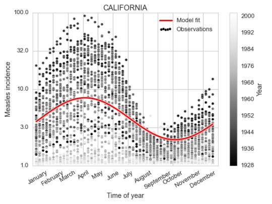
It is fairly clear both from looking at the data and the fit of the cosine curve how the measles incidence (which is defined as number of cases per 100 000 people) changes over the year, peaking in early April.
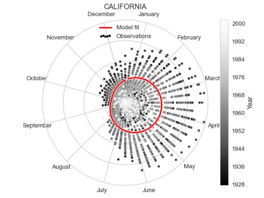
As an alternative representation of the same plot, we can put it in polar coordinates to emphasise the yearly periodicity.
We fitted the model such that we will have a different seasonal component for each state. To visualize them all at once we take the seasonal component for each state, assign a color value based on it’s level on a given week, and put this on a map. We do this for every week and animate this over the year, resulting in the video below.
In the video green corresponds to high incidence and blue to low. There is an appearance of a wave starting from some states and going outwards towards the coasts. This means some states have different peak times of the measles incidence than others. We can find the peak time of a state’s seasonal component by doing some simple trigonometry.
So $ \phi $ will (after scaling) give us the peak time for a state (meaning the offset of the cosine curve). After extracting the offset for each state, we make a new map illustrating the peak times of measles incidence over the year.

The color scale ranges from week 10 (white) in early March to week 14 (black) in early April. We didn’t provide the model with locations of the states, but the peak times do seem to cluster spatially.
Methodology
I also want to show how I did this.
%pylab inline # Parsing and modelling import pandas as pd import seaborn as sns import statsmodels.formula.api as smf # Helps with datetime parsing and formatting from isoweek import Week import calendar # For plotting the spline from patsy.splines import BS from scipy import interpolate # For creating US maps import us from matplotlib.colors import rgb2hex from bs4 import BeautifulSoup
The data we use from the Tycho project comes in a csv which we parse with Pandas.
measles = pd.read_csv('MEASLES_Incidence_1928-2003_20150413093130.csv', skiprows=2) measles.index = pd.DatetimeIndex([Week(*t).monday() for t in zip(measles.YEAR, measles.WEEK)]) measles = measles.drop(['YEAR', 'WEEK'], 1) measles = measles.convert_objects(convert_numeric=True)
Now we have tabular data of this form
measles.iloc[:5, :5]
ALABAMA
ALASKA
ARIZONA
ARKANSAS
CALIFORNIA
1928-01-02
3.67
NaN
1.90
4.11
1.38
1928-01-09
6.25
NaN
6.40
9.91
1.80
1928-01-16
7.95
NaN
4.50
11.15
1.31
1928-01-23
12.58
NaN
1.90
13.75
1.87
1928-01-30
8.03
NaN
0.47
20.79
2.38
This is a large matrix of states vs time points with incidence in each cell. For making a linear model we would prefer to have it in a form where each row is an observation, and the columns giving variables used.
year = [] week = [] state = [] incidence = [] for i in measles.index: for c in measles.columns: year.append(i.year) week.append(i.week) state.append(c) incidence.append(np.log10(measles.ix[i, c] + 1)) data = pd.DataFrame({'year': year, 'week': week, 'state': state, 'incidence': incidence}) data.iloc[:5, :5]
incidence
state
week
year
0
0.669317
ALABAMA
1
1928
1
NaN
ALASKA
1
1928
2
0.462398
ARIZONA
1
1928
3
0.708421
ARKANSAS
1
1928
4
0.376577
CALIFORNIA
1
1928
We can now use statsmodels to define and fit the linear model
df = 12 d = 3 model = smf.ols('incidence ~ bs(year, df=df, degree=d, include_intercept=True) \ + np.cos(2 * np.pi / 52 * (week - 1)) : C(state) \ + np.sin(2 * np.pi / 52 * (week - 1)) : C(state) \ - 1', data=data).fit()
To be able to use the parameters fitted for the spline, a bit of plumbing is needed. We let patsy and statsmodels pick the knots for the spline, for which the coefficients are fitted by the OLS model. One could calculate these knots directly from the data. But it is simpler to grab the function for picking the knots from patsy. Then we extract the spline coefficients from the model parameters.
my_bs = BS() my_bs.memorize_chunk(data.year, df=df, degree=d, include_intercept=False) my_bs.memorize_finish() coeffs = [] conf_int= model.conf_int(alpha=0.05) for i in range(df): parameter_name = 'bs(year, df=df, degree=d, include_intercept=True)[{}]'.format(i) coeffs.append(model.params[parameter_name]) knots = my_bs._all_knots tck = (np.array(knots), np.array(coeffs), 3)
The interpolate function from scipy uses triples of knots, coefficients and the degree of the basis polynomials as a parameter, which is used to evaluate any point in the domain of the spline.
x = np.arange(1928, 2004) y = interpolate.splev(x, tck)
Once we have done this, we can create the first figure.
figsize(8, 6) # For legend with high alpha dots plt.scatter(-1, -1, c='k', edgecolor='w', label='Observations') plt.scatter(data.year, data.incidence, alpha=0.01, edgecolor='w', c='k'); plt.plot(x, y, c='w', lw=5); plt.plot(x, y, c='r', lw=3, label='Model fit'); plt.xlim(x.min() - 1, x.max() + 1); plt.xlabel('Year') plt.ylim(0, 2.); loc, lab = plt.yticks() lab = [np.round(10 ** l) for l in loc] plt.yticks(loc, lab); plt.ylabel('Measles incidence'); plt.legend(scatterpoints=5) plt.title('U.S. Wide trend'); plt.tight_layout(); plt.savefig('per_year.png');

Next we extract the periodic component parameters for a given state and define a function of the week of the year.
state = 'CALIFORNIA' alpha = model.params['np.cos(2 * np.pi / 52 * (week - 1)):C(state)[{}]'.format(state)] beta = model.params['np.sin(2 * np.pi / 52 * (week - 1)):C(state)[{}]'.format(state)] def periodic(week): return alpha * np.cos(2 * np.pi / 52 * (week - 1)) + \ beta * np.sin(2 * np.pi / 52 * (week - 1))
And using this we can create the second plot
figsize(8, 6) fig = plt.figure() ax = fig.add_subplot(1, 1, 1) plt.scatter(data.query('state == "{}"'.format(state)).week, data.query('state == "{}"'.format(state)).incidence, c=data.query('state == "{}"'.format(state)).year, alpha=0.99, s=30, cmap=cm.Greys_r, edgecolor='w', label='Observations', color='k') x = np.linspace(1, 52, 100) year = 1950 yy = np.maximum(periodic(x) + y[year - 1928], 0) plt.plot(x, yy, lw=5, c='w') + \ plt.plot(x, yy, lw=3, c='r', label='Model fit'); plt.xlim(x.min() - 1, x.max() + 1); plt.ylim(0, 2); loc, lab = plt.yticks() lab = [np.round(10 ** l) for l in loc] plt.yticks(loc, lab); plt.ylabel('Measles incidence'); xtloc = 1.5 + 52. / 12 * np.arange(0, 13) plt.xticks(xtloc, calendar.month_name[1:], rotation=30); plt.xlabel('Time of year'); plt.title(state) plt.legend(scatterpoints=5) plt.colorbar(label='Year'); plt.tight_layout(); plt.savefig('ca_per_week.png');

To create the polar version of the same plot we don’t need to change much, just define the axis to be polar, and transform the x range from 1 to 52 to be between 0 and $2\pi$. Though we do also flip the orientation and rotate the 0 of the polar coordinates since having January 1st on top feels more intuitive, as well as clockwise direction.
fig = plt.figure() ax = fig.add_subplot(111, projection='polar') ww = data.query('state == "{}"'.format(state)).week plt.scatter(np.pi / 2.0 - 2 * np.pi * ww / 52, data.query('state == "{}"'.format(state)).incidence, c=data.query('state == "{}"'.format(state)).year, alpha=0.99, s=30, cmap=cm.Greys_r, edgecolor='white', color='k', label='Observations') x = np.linspace(1, 52, 100) year = 1950 yy = np.maximum(periodic(x) + y[year - 1928], 0) xx = np.pi / 2.0 - 2 * np.pi * x / 52 plt.plot(xx, yy, lw=5, c='w'); plt.plot(xx, yy, lw=3, c='r', label='Model fit'); plt.ylim(0, 2); month_locs = np.pi / 2.0 + 2 * np.pi / 24 - 2 * np.pi / 12 * np.arange(13) ax.set_xticks(month_locs); ax.set_xticklabels(calendar.month_name); ax.set_yticks([0.5, 1.0, 1.5, 2.0]); ax.set_yticklabels([''] * 4); ax.set_title(state); plt.legend(scatterpoints=5, loc='upper center') plt.colorbar(label='Year'); plt.tight_layout(); plt.savefig('ca_per_week_polar.png');

Now, the US state map (also known as a choropleth). This was WAY more complicated than I tought it would be! I imagined there would be some simple functions in matplotlib or similar package. But the ones I tried required map files I wasn’t familiar with and some of them I couldn’t get running. In particular I think GeoPandas is interesting, but I could not get it working.
After trying a bunch of packages and approaches, at some point I ended up with an SVG file with defined state paths. I’m not completely sure were it came from, it might have been from simplemapplot. Just to be sure, I put the SVG file up on a gist.
Before going on to making the visualization, let’s put all the states’ seasonal functions in a dictionary so we can easily use them.
def make_periodic(state): alpha = model.params['np.cos(2 * np.pi / 52 * (week - 1)):C(state)[{}]'.format(state)] beta = model.params['np.sin(2 * np.pi / 52 * (week - 1)):C(state)[{}]'.format(state)] def periodic(week): return alpha * np.cos(2 * np.pi / 52 * (week - 1)) + \ beta * np.sin(2 * np.pi / 52 * (week - 1)) return periodic periodics = {} for state in data.state.unique(): periodics[state] = make_periodic(state)
Ok, so the approach that we take is to use BeautifulSoup to parse and edit the SVG file.
svg = open('output_state_map.svg', 'r').read() soup = BeautifulSoup(svg)
The way to change the colors is to change the style attributes of each state element in the SVG. The inspiration for this strategy was this IPython notebook where the same is done on an Iowa map.
First we set up a baseline path style which we will append the color to.
path_style = "font-size:12px;fill-rule:nonzero;stroke:#000000;" + \ "stroke-width:1;stroke-linecap:butt;stroke-linejoin:bevel;" + \ "stroke-miterlimit:4;stroke-opacity:1;stroke-dasharray:none;" + \ "marker-start:none;fill:"
So what we do with this is to loop over the weeks, and for each week color all the states according to their seasonal incidence functions. The colors are converted to hex codes and assigned to the corresponding state’s path. We save one SVG per week.
for w in range(1, 53): all_states = soup.findAll(attrs=) for p in all_states: state = us.states.lookup(p['id']).name.upper() p['style'] = path_style + rgb2hex(cm.winter(periodics[state](w) + 0.4)) h = soup.find(attrs={'id': 'hdlne'}) mnd = Week(1990, w).monday() h.string = calendar.month_name[mnd.month] fo = open("/tmp/state_map_.svg".format(w), "wb") fo.write(soup.prettify()); fo.close()
The modified SVG files are saved as if they are HTML files by BeatifulSoup. The files will still be viewable in web browsers. But for using conversion tools or vector graphics editing tools these need to be in proper SVG format. This is farily easy to fix, one just need to remove the <body> and <html> tags from the file.
%%bash for f in /tmp/state_map_*.svg; do grep -v "body\|html" $f > $f.tmp mv $f.tmp $f done
Once this has beed fixed, we can create an animated gif using the convert command from ImageMagick.
%%bash convert -delay 6 -loop 0 /tmp/state_map_??.svg animated_state_map.gif
Because having a constantly animating gif on the page was extremely annoying, I converted it to a video using ffmpeg.
%%bash ffmpeg -f gif -i animated_state_map.gif animated_state_map.mp4
The final bit is making the map with the seasonal peak times. We simple solve the equations described above for each state to find te offset of the cosine function.
state_peak = {} for state in data.state.unique(): alpha = model.params['np.cos(2 * np.pi / 52 * (week - 1)):C(state)[{}]'.format(state)] beta = model.params['np.sin(2 * np.pi / 52 * (week - 1)):C(state)[{}]'.format(state)] rho = np.sqrt(alpha ** 2 + beta ** 2) theta = np.arccos(alpha / rho) peak_week = theta / (2 * np.pi) * 52 state_peak[state] = peak_week state_peak = pd.Series(state_peak)
Just like above we color the states by the value.
svg = open('output_state_map.svg', 'r').read() soup = BeautifulSoup(svg) h = soup.find(attrs={'id': 'hdlne'}) h.string = 'Peak incidence' h['x'] = 600 all_states = soup.findAll(attrs=) for p in all_states: state = us.states.lookup(p['id']).name.upper() peak = state_peak[state] col = rgb2hex(cm.Greys((peak - state_peak.min()) / (state_peak.max() - state_peak.min()))) p['style'] = path_style + col fo = open("measles_spread.svg".format(w), "wb") fo.write(soup.prettify()); fo.close()
To add the color bar I edited the resulting SVG file in Adobe Illustrator.